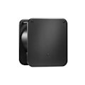
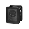
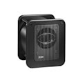
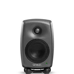
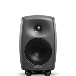
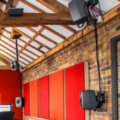
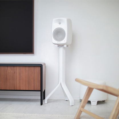
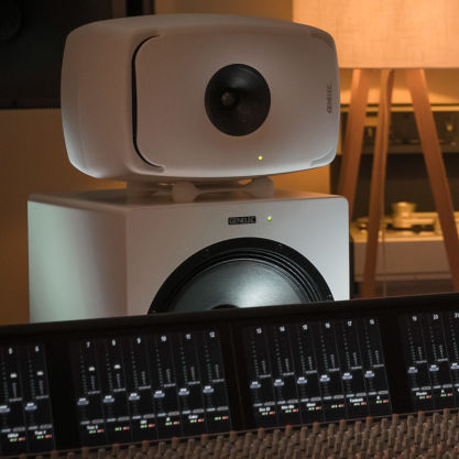
For those demanding a compact subwoofer with extended LF performance, generous SPL and professional bass management, the 7050C is the natural choice.
7050C
Studio Subwoofer

Active Crossovers

Bass Management System

SPL
103 dB

Frequency Response
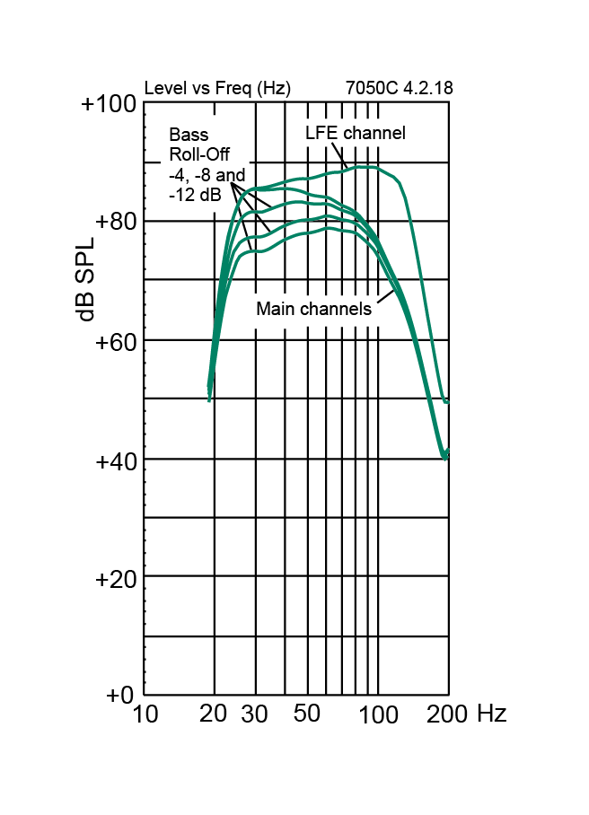
24 Hz - 85 Hz (-6 dB)

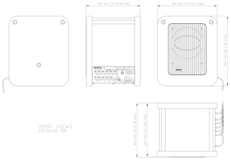
Dimensions
H 410 x W 350 x D 319 mm, (view in inches)

Perfect partners
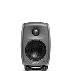
The perfect partner for any nearfield monitor, particularly our own 8010, 8020 and 8030 models, the 7050C boasts a number of improvements over its A and B predecessors, including onboard bass management, lower distortion, a universal switched-mode power supply, and an increased maximum SPL of 103 dB.

Stereo or multichannel
With five input and output channels with 85 Hz filtering - plus a 120 Hz LFE input - the 7050C is equally suited to stereo or multichannel work, and its laminar spiral enclosure provides extended LF response down to 24 Hz with impressively low distortion. Rear panel DIP switches control subwoofer phase and LF roll-off, engage the +10 dB LFE level, and also activate and control the sensitivity of the 7050C’s ISS power-saving mode.

SPL
103 dB

Amplifier Power
130 W Bass (Class D)

Frequency Response
24 Hz - 85 Hz ("-6 dB")

Driver Dimensions
⌀ 205 mm Bass (view in inches)

Dimensions
H 410 x W 350 x D 319 mm, (view in inches)

Weight
17.3 kg / 38.1 lb

Connections
6 x XLR Analog Input
5 x XLR Analog Output
7050C Studio Subwoofer
Studio Subwoofer
Technical Specifications
For those demanding a compact subwoofer with extended LF performance, generous SPL and professional bass management, the 7050C is the natural choice.

System Specifications
Frequency Response
Low cutoff -6dB
24 Hz
High cutoff -6dB
85 Hz
SPL
Short term max SPL Maximum short term sine wave SPL output averaged from 30 to 85 Hz, measured in half space at 1 meter.
≥103 dB
Self-generated noise
Self-generated noise Self generated noise level in half space at 1 m on axis (A-weighted).
≤5 dB SPL
Weight
Weight17.3 kg (38.1 lb)
Dimensions
Height
410 mm
Width
350 mm
Depth
319 mm
Enclosure
Enclosure material
MDF
Enclosure type
Reflex port
Drivers
Driver type
Cone
Magnetically shielded driver.
Diameter
205 mm
Harmonic distortion
Amplifier Section
Amplifiers
130 W Class D
Mains voltage
100-240 VAC 50/60Hz
Power consumption
ISS Active
≤0.5 W
Idle
≤11 W
Full output
150 W
Signal processing section
Connectors
6 x Input 5 x input connectors XLR female, 10 kOhm balanced.
1 x LFE IN connector.
5 x Output XLR male output connectors.
Product Variants
Product codes
For even more technical details please see product operating manual.
Key Technologies

Active Crossovers

Bass Management System

Laminar Spiral Enclosure (LSE™) Technology

Protection Circuitry

Optimised Amplifiers

Room Response Compensation
Active crossover operating at low signal levels.

Audio electronic crossovers allow the audio signal to be split into separate frequency bands that are separately routed to individual power amplifiers, which are then connected to specific transducers optimised for a particular frequency band.
Active crossovers come in both digital and analogue varieties. Genelec digital active crossovers include additional signal processing, such as driver protection, delay, and equalisation.
Genelec analogue active crossover filters contain electronic components that are operated at low signal levels suitable for power amplifier inputs. This is in contrast to passive crossovers that operate at the high signal levels of the power amplifier's outputs, having to handle high currents and, in some cases, high voltages.
In a typical two-way system the active crossover needs two power amplifiers — one for the woofer and one for the tweeter.
The active crossover design offers multiple benefits:
- The frequency response becomes independent of any dynamic changes in the driver's electrical characteristics or the drive level.
- There is increased flexibility and precision for adjusting and fine-tuning each output frequency response for the specific drivers used.
- Each driver has its own signal processing and power amplifier. This isolates each driver from the drive signals handled by the other drivers, reducing inter-modulation distortion and overdriving problems.
- The ability to compensate for sensitivity variations between drivers.
- The possibility to compensate for frequency and phase response anomalies associated with a driver’s characteristics within the intended pass-band.
- The flat frequency response of a high-quality active loudspeaker is a result of the combined effect of the crossover filter response, power amplifier responses and driver responses in a loudspeaker enclosure.
Using the active approach enables frequency response adjustments and optimisation of the full loudspeaker system, placed in various room environments, without expensive external equalisers. The end result is a simpler, more reliable, efficient, consistent and precise active loudspeaker system.
Bass Management System handles multichannel low frequency content.

The principle of bass management is that the bass content of the main channels and the Low Frequency Effect (LFE) channel are directed and reproduced only by loudspeakers capable of handling them, whether they are main system loudspeakers or one or more subwoofer(s).
In stereo reproduction, signals from 20 Hz to 20 kHz need to be replayed. Large multi-way monitoring systems will reproduce such a wide bandwidth evenly. With multichannel audio, professional and consumer audio systems must also be able to reproduce audio between 20 Hz and 20 kHz for each channel. To achieve this, main monitors, subwoofers and crossover electronics should work together.
A Bass Management system uses either analogue electronic circuitry or software based filtering which will filter low frequency information from the main channels and route that information to one, or more, subwoofer feed.
The dedicated LFE channel can also be monitored via that subwoofer and added to the low frequencies of the other main channels. Therefore, the Bass Management’s basic and main goal is to ensure that the entire audio bandwidth of all channels can be accurately monitored.

The benefits of the Bass Management System:
- The subwoofer extends the system frequency response down the lower limit of the audible range
- Monitor can produce a higher maximum sound level when not reproducing low frequencies
- Optimized low frequency reproduction by selecting adequate subwoofer location; monitors can also be placed more freely
- Subwoofer’s output are aligned in level and phase with monitors allowing flat and accurate reproduction down to 19 Hz and across the crossover point
- LFE channel output level (0 or +10 dB re. main channels) can be selected for accurate reproduction depending on the source type
- The ability to bypass the subwoofer allows to evaluate the audible impact of the subwoofer
Highly efficient Laminar Spiral Enclosure (LSE™) provides accurate low frequency reproduction.

The demands placed on subwoofers over the last years have increased substantially to the point where traditional design concepts are no longer valid. For Genelec, in order to achieve the absolute best performance possible, bold initiatives must be taken.
Drawing on years of acoustic research and knowledge, Genelec's engineering group accepted the challenges placed upon them in the beginning of the 21st Century. The totally unique, curvilinear shape of the LSE™ Series Active Subwoofer enclosure is the revolutionary patented result of their efforts.
All of the Genelec LSE™ series subwoofers feature this innovative Laminar Spiral Enclosure™ (LSE™) bass reflex cabinet. It provides excellent laminar flow characteristics with minimal turbulence noise and enables an optimal packing of a very long reflex tube into a small space.

The learnings from the LSE Technology are also utilized in the reflex port design of our aluminium enclosure products.
The spiral-shaped design yields an extremely rigid enclosure exterior while also forming the subwoofer's integral port. The fact that one is part of the other means that air flow in and out of the enclosure's interior through the port is totally unrestricted. This results in an extraordinarily accurate and responsive low-frequency system with measured second and third harmonic distortion levels typically better than 30 dB below the fundamental.

When combined with Genelec stereo and multichannel bass management active electronics, the LSE™ Series Subwoofers provide a low-frequency listening experience like no other. The result is a product range with impeccable technical performance: The Genelec LSE subwoofer range is unique, complete, functional, different from any other products on the market, and consistent.
Sophisticated drive unit protection circuitry for safe operation.

When working in critical audio production environments it is essential that monitoring systems remain reliable and functional at all times. One of the main reasons behind Genelec’s excellent success in broadcasting environments is the reliability of our products and a key element behind the reliability is the internal protection circuitry found in all products since 1978.
The protection circuitry prevents driver failures by detecting signal levels, and in case of sudden peaks or constantly too high levels, taking the signal level down automatically. Of course this feature does not affect the sound quality in any way when working within the specifications of the loudspeaker, but only prevents inadequate input signals from breaking the loudspeaker.
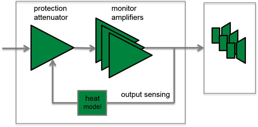
Protection circuitry features and benefits:
- Reduces the output level when required, (e.g. when driver voice coil temperature reaches the safe limit), which highly improves system reliability.
- Appropriate protection circuitry design in every loudspeaker and subwoofer enables the maximisation of system output sound level.
Each transducer is driven by its own optimised amplifier.

Audio electronic crossovers allow to split the audio signal into separate frequency bands that can be separately routed to individual power amplifiers, which are then connected to specific transducers optimised for a particular frequency band.
In a typical 2-way loudspeaker system, the active crossover needs two power amplifiers — one for the woofer and one for the tweeter. The power amplifiers are connected directly to the drivers of an active loudspeaker, resulting in the power amplifier’s load becoming much simpler and well known. Each driver-specific power amplifier has only a limited frequency range to amplify (the power amplifier is placed after the active crossover) and this adds to the ease of design.
The active design principle offers multiple benefits:
- The power amplifiers are directly connected to the speaker drivers, maximising the control exerted by the power amplifier’s damping on the driver’s voice coil, reducing the consequences of dynamic changes in the driver electrical characteristics. This may improve the transient response of the system.
- There is a reduction in the power amplifier output requirement. With no energy lost in the passive crossover filter components, the amplifier power output requirements are reduced considerably (by up to 1/2 in some cases) without any reduction in the acoustic power output of the loudspeaker system. This can reduce costs and increase audio quality and system reliability.
- No loss between amplifier and driver units results in maximum acoustic efficiency.
- Active technology can achieve superior sound output vs. size vs. low frequency cut-off performance.
- All loudspeakers are delivered as a factory aligned system (amplifiers, crossover electronics and enclosure-driver systems).
Precise room response compensation for optimizing in-room performance.

The interaction between room acoustic and loudspeaker radiation is complex. Each room changes somewhat the monitor’s response in a unique way, e.g. reflective vs. damped rooms, or placement against a wall vs. on a stand away from the walls.
All Genelec loudspeaker systems feature room response adjustments to compensate for the room influences and retrieve a flat frequency response at the listening position.
Analogue Systems
Genelec analogue loudspeaker systems provide versatile Room Response Controls. They include (depending on models):
- Bass Roll-Off and Bass Tilt
- Treble Tilt and Treble Roll-Off
- Bass Level
- Midrange Level
- Treble Level
- Desktop Control

At low frequencies two main controls are provided. The Bass Tilt control, which acts as a shelving filter together with the Bass Roll-off control allowing you to optimize the low and very low frequency response of the system in different installations. Bass, midrange and treble level controls are provided in large systems. These controls allow to optimize the relative balance between the various pass bands.
The operating manual and datasheet of each loudspeaker contains a list of preferred room response control settings for different installations. These have been specified out of long practical experience and measurements of various kind of typical acoustic environments.
Smart Active Monitor (SAM™) Systems
Genelec SAM Systems offer a comprehensive, solution-oriented, intelligently networked product range which all feature Genelec Loudspeaker Manager (GLM™) software and its automatic calibration system called AutoCal™.
Genelec AutoCal provides the industry’s first integrated process for complete automated measurement, analysis, and adjustment of every monitor on the GLM control network. The system measures the response in the listening area and applies relevant compensation in the low and low-mid frequencies to minimise the detrimental room acoustic anomalies as well as the differences between various listening positions. AutoCal also aligns relative levels, time-of-flight, as well as adjusts correct crossover phase (called AutoPhase) for all subwoofers on the network.

The Acoustic Response Editor provides accurate graphical display of the measured response, filter compensation and the resulting system response for each monitor, with full manual control of acoustic settings.
References
Documentation
Documents
Operating Manual 7050C Quick Setup Guide 7050C Brochure 7050C Genelec Home Studio Audio Monitoring Guide (2023) Classic Active Monitoring Series Catalogue 2018 Genelec 7050C Operating Manual - Chinese Genelec Home Studio Audio Monitoring Guide (German version)FAQ
Connecting the 7050B Subwoofer
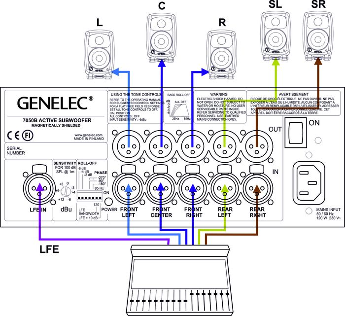
The 7050B subwoofer has balanced XLR IN/OUT connector pairs for five main channels and a dedicated LFE input connector for the LFE channel. Connect the signal cables from your source to the female XLR "IN" connectors on the lower connector row. Next connect XLR cables from the corresponding "OUT" male XLR connectors on the upper row to the input connectors of each 8020C monitor.
Turn the volume control knob on all 8020C’s monitors fully clockwise and switch the "Bass Roll-off" dip switch (switch 2) on all 8020C’s to "ON". This switch actuates an 85 Hz high-pass filter on the 8020C’s matching them to the main channel low-pass filter of the 7050B.
Alternatively you can connect to the 7050B a stereo pair of 8020C monitors by routing the signal cables from the source to the input connectors of the main monitors and an another pair of cables from the main monitors' output connectors to the "IN" connectors on the 7050B. In this configuration the volume controls on the main monitors affect the playback level of the 7050B too. The "Bass Roll-off" switch on the main monitors must also be switched to "ON" (switch 2).
Why to Align a Multichannel System?
The main goal in the alignment of a multichannel system is to set the subwoofer output level the same as the sound output level of the main monitor system. The LFE output of the mixing desk or decoder should be connected to the LFE input on the subwoofer.
For the 7050B, 7060B, 7070A, 7071A, 7073A products:
The LFE input has the same sensitivity as all other signal inputs unless the ‘LFE +10 dB’ DIP switch is ON. The switch is used when there is no +10 dB gain in the LFE channel output. The switch is set to 0 dB when there is already a +10 dB additional gain in the LFE channel output.
What reference level to use?
To ensure repeatable results in the finished product, the SMPTE (Society of Motion Pictures and Television) has set standard monitoring levels for cinema post-production work. The SMPTE reference level at the listening position is 85 dB SPL, on C weighted/slow scale. The input signal to the monitors is -20 dB FS (rms) full bandwidth pink noise. The SMPTE RP200 uses an electrical reference level of -18 dB FS.
For music mixes, there are no standardized levels. The level that the engineer chooses is arbitrary and based on personal taste, as is the level chosen by the end user. The level is typically 75 dB SPL for television audio work and 75-95 dB SPL for music production work.
Manual calibration of the level and frequency response
Monitors are first calibrated to have flat response at the listening position. This is achieved by doing the following:
Calibrate the monitor frequency responses using an acoustical measuring system with the subwoofer bypassed or disconnected. Then connect the Genelec subwoofer and adjust the subwoofer level, bass roll-off and phase so that the measured combined frequency response of the subwoofer and the monitor extends flat to the LF cut-off of the subwoofer, paying special attention to the subwoofer to monitor crossover point.
Alternative level calibration methods
If acoustic measurement system is not available for aligning the system, then follow the guidelines that can be found in the operating manual for adjusting the frequency response:
Level calibration using a ⅓ octave real time analyzer, broadband pink noise and an SPL meter
Connect the Genelec 5.1 system and play broadband pink noise signal (20 Hz – 20 kHz) through the subwoofer and one of the monitors, for example the centre channel monitor. Adjust the acoustic settings in the subwoofer and monitors so that the level in each band on the RTA analyser reads the same value. Then, set the output level of each channel to give the same acoustical level at the listening position.
Level calibration using filtered pink noise and an SPL Meter
You need to have filtered pink noise to calibrate the levels of the subwoofer and the main channels. You can use a copy of the TMH Corporation 'Multichannel Studio Test Tape' that includes the various test signals required.
Pink noise filtered to a passband 500 Hz to 2 kHz is used for adjusting the monitor levels, and between the frequency range 20 Hz to 80 Hz is used for calibrating the subwoofer level. Please note: If the standard recorded level of filtered pink noises is -18 dBFSrms for SMPTE RP200's (-20 dBFSrms for SMPTE) and then the absolute level calibration can be made so that the sound level meter reads a level 2 dB lower than specified for broadband pink noise. This is because there is less energy due to band limiting of the band-pass noise.
- Connect to monitors and play the 500 Hz to 2 kHz filtered pink noise. Set the SPL Meter to C-weighting and slow reading. Adjust each main channel individually to have the same SPL level at the listening position.
- Play 20 to 80 Hz filtered pink noise through the subwoofer. The correct adjustment gives a reading 3dB lower than the one for the monitors because the C weighting lowers the reading in the SPL meter at those frequencies. If there is no HP filter in the SPL meter then the reading should be the same as for the monitors.


